
|
|
DQancDWC
|
| Capable of extending the noise reduction area.
( see also Active Noise
Control 101 ) (1) Control only the direct or with reflecting waves from the noise source. (2) Remove the reflection component from the secondary path. (3) Derive an optimum reference signal. (4) High sampling frequency to minimize the system delay. | |
| Maximum configuration : Case(4-4-4) 4ch reference inputs, 4ch control outputs, 4ch error inputs with howling cancellers. | |
| Online system identification | |
| Ex_Tool system configuration (1) DSP : RU-DQ13 (1 board) (2) AD/DA : RU-AX84 (2 boards) (3) Chassis : 5 slots | |
| Programmable parameters (1) Number of input & output channels : 1 - 4ch (2) Howling canceller On/Off (3) Reference signal Cross-talk Canceller On/Off (4) Sampling frequency : 500Hs - 24KHz (5) Analog filter cut-off frequency : 100 - 20KHz (6) Number of Fir taps : max.1024 (7) Step-size parameter and leakage for ADF (8) Noise level for System identification (9) Number of cycles for System identification (10) Frequency band to control. | |
| Control algorithm : Leaky Filtered-X LMS / NLMS | |
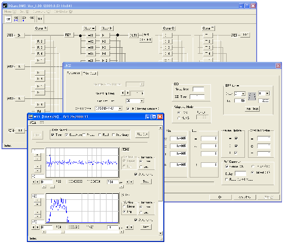
| Coefficient viewer at run-time | |
| Windows 2000/XP/Vista/7 | |
| Software name : DQancDWC (RU-DQ13 Active Noise Control Direct Wave Control) |
| Channel Configration | Sampling Frequency | C, T, H max. number of taps | W max. number of taps |
| CASE(4-4-4) |
24KHz |
180 |
220 |
|
12KHz |
380 |
600 |
|
|
4KHz |
1024 |
1024 |
|
| CASE(2-2-2) |
24KHz |
460 |
480 |
|
12KHz |
800 |
1024 |
|
| CASE(1-1-1) |
24KHz |
512 |
512 |
Caution) Not available on same conditions, like updating all coefficients, operating howling cancellers, etc.
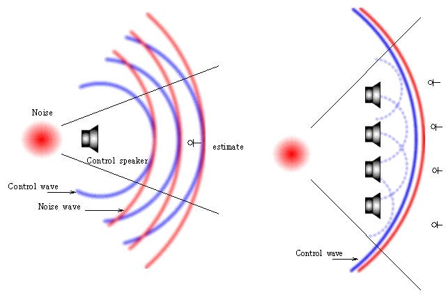
In case of Feed-forward Active Noise Control, in which a
reference signal goes in and an anti-phase signal goes out of a secondary sound
source (a control sound source) to make a quiet zone, it is recommended for the
noise source, the secondary sound source and the controlled quiet point
to align on the same strait line.
It's easy to control the fan noise in a duct chamber, in
which the noise sound wave is plane. Just adjust the control sound wave to the noise sound wave at
one control point, so the quiet area is spreading far and wide downstream.
But, in a 3-dimensional space, if the control sound wave hit from one
direction to the noise sound wave propagating to the other direction with some
angles, the effective area would be limited within only a fraction of the
wavelength. And outside of
the control point would be even worse. Therefore, it's ideal that the secondary
sound source is set on the line through the noise source and the control point,
and it should be set around the noise source as closely as possible.
That's why a control system needs to have a sufficiently-little system delay time to overcome the
propagation time of the noise sound wave. To achieve that, it's an important
factor to get the sampling frequency high and reduce the delay time of the
anti-aliasing analog filters by getting the cut-off frequency high. When the
sampling frequency is high, it's necessary for the FIR filters to have larger
number of taps, so a more powerful DSP system would be needed.
Even if you can't set the control speaker close to the noise source, you can adjust
the
control sound wave to the noise sound wave by setting more control speakers and
error microphones.
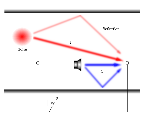
In Active Noise Cancelling, a sound propagation path from a noise source to a
controlled point (path A) has a direct path and some reflection paths as well.
The noise sound wave reaches to the controlled point directly and indirectly by reflecting at
surrounding walls before its arrival at the controlled point. Another path from
the control speaker to the controlled point (path B) is the same. These
reflecting sound waves have a large impact on the control effect.
In the case of path A, the reflecting sound violates the rule, which is
explained above that a control speaker should
be on a line through the noise source and the controlled point, and
that makes a less quiet or louder zone because the reflected sound waves propagate to
the control line with some angles. So, it's more advantageous to control only the
direct sound.
In the case of path B, the reflecting sound makes the length of the inverse filter
longer. Suppose the path from a noise source to a control point is "T", and the
path from a control speaker to the control point is "C", the transfer function
of a control inverse filter "W" is calculated by equation W = -T/C. If the characteristic of
"C" contains a reflection, "W" would have a pole, which makes the
impulse response longer and the number of FIR taps larger, and it becomes harder to
execute the calculation at a high sampling rate.
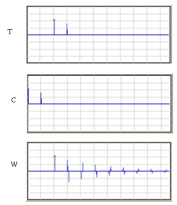
The following figure shows that each "T" and "C" has one reflection
path, and
the impulse response of "W" goes infinite. Redec DQancDWC has an
architecture "Direct
Wave Control Algorithm" that removes reflection characteristics and controls only
direct sound waves, and makes the Active Noise Canceller
more effective.
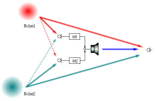
When you try to control a space with several noise sources, you need to input the same number of reference signals as the number of noise sources. As in the following figure, when there are two noise sources, you can control a point with two reference inputs and two control filters. But in many cases, there are cross-talk paths between the paths from the noise sources to reference inputs. These cross-talk paths make the impulse response of the control filters longer, because the characteristic of the path matrix of the noise source side comes the denominator factor, and the cross-talk functions make poles in the characteristics of the inverse filters. If you can vanish the cross-talk paths and input the closest reference signal as a reference, the poles in a control inverse filter also vanish and the filter length becomes shorter with less filter taps.
Each reference signal has a correlated
component with another reference signal, so when you draw the reference which is
closest to one noise source and can cancel the correlated component in another
reference signal, you can clear out the
cross-talk paths.
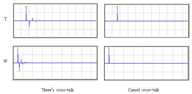
The figures below show a control inverse filter W with a cross-talk path
in the reference field, and without a cross-talk. W without a cross-talk goes into just an
impulse. A redundant part of the lengthened W would deteriorate the control
effect at the surrounding area of
the controlled point, and it would be a drawback in terms of extending the noise
reduction zone.
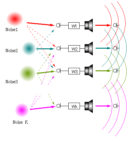
When an array of control speakers are set on
a wall like in the case of road noise control, the control system might be
configured with an array of "Case(1-1-1)" systems due to circumstances of
hardware scale. But, each control system might interfere with the others and go
unstable. If the cross-talk paths between each system could be vanished, this
problem would be solved.
Canceling cross-talk paths means getting the nearest reference signal, so it
is
to achieve the rule of "(1)control speaker position", and it
leads to the situation in which the noise reduction area is extended.
Redec "DQancDWC" has a function of
Cross-talk Canceller, which vanishes cross-talk paths on the noise source
side, derives
optimum reference signals, and makes it an ideal system in
Multi-Channel Active Noise Control.
Usually, an error microphone (the microphone at a controlled and estimated point ) should be placed appropriately far from the control speaker (the far-fiels). But, sometimes its location is limited to an area near the speaker (the near-field) due to the system size. If the error microphone is set close to the control speaker, the control effect appears only at the area near the error microphone, not till the far end because of the following reasons.
a) The sound field near the speaker (the near-field) is
linearly turbulent due to the mechanical structure driving the diaphragm and
supporting itself. The microphone near the the speaker cannot be used for controlling downstream.
b) Sound power decays exponentially with distance. It needs only tiny
sound power to control the field near the speaker (the near-field). To control the far
end (the far-field), much more power
is needed.
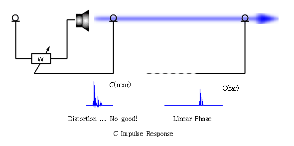
Redec software "DQvmic", which runs on Ex_Tool, solves this problem and makes ANC system a compact one.
Recipe) First, set an error microphone at a far end (a
far-field),
and measure the secondary transfer function C(far). It doesn't cause a big
problem even if C(far) characteristically changes afterwards. The far end transfer function could
be explained as a transfer function which is the result when one transfer
function near the control speaker is shifted with power-decreasing and
phase-increasing by distance. Inversely, C(far) can be back-shifted
to an area near the control speaker (the near-field) because of its
linearity. Back-shift the impulse-like part of C(far) and compose C(near) transfer
function. Use C(near) instead of C(far) in the W-updating
algorithm for the control. In this method, there is no effect around the
are near the error microphone, and it even gets worse,
but the reduction field spreads widely at the far end. This means just controlling a
VIRTUAL FAR point, where there is a Virtual Microphone.
Using this method, as well as being able to make the system compact, you will
get an outgrowth as follows.
To achieve maximum effect, the noise source, the secondary sound
source and the error microphone align on one straight line (called a control line).
The
reduction area spreads downstream of the virtual control point and the
effective result can be expected. When the noise source moves out of the control line, decreasing control effect
might be expected. But, the distance between the reference signal input point
and control signal output point is very little compared with the distance between the
noise source and the control point which spreads far, so the controller
input-output distance seems to be a tiny point. When the noise source moves, the
control area also moves to the point-symmetric direction around the controller
as the origin, sustaining the width of the reduction zone.
|
Last update : 2010/06/19
|